Impedance controlled PCB
Impedance controlled PCB
Technical parameters
*Controlled dielectric
*Controlled impedance
*Design coupons
*Test coupons
*Polar CITS500
*Tolerance +/-10%
*Differential impedance
*Single end impedance
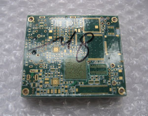
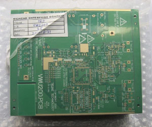
Actual PCB case
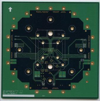
It's a typical sample we offer for high power electronics:
230*230mm=1 PCB FR-4 TG170 4 Layers 35 um copper each layer 2.4mm finished thick
min.track/space: 4/4mil Min.hole 0.25mm ENIG Surface finish
L1 and L4: track /space 5.1/6mil, 90+/-10% ohm differential impedance
L1, L2 and L4, track /space 6.1/7.8mil, 100+/-10% ohm differential impedance
Related PCB products & Services:
*High Tg 170
*High CTI 600V
*Multi-layer
*Blind vias, Half hole, Via in pad,
*countersunk hole *Gold finger
*BGA,CSP,QFN
*ENIG, HASL, Immersion Silver, OSP
*Prototype
*Mass production
*MOQ: 1 PCB
*Door to door shipmen


